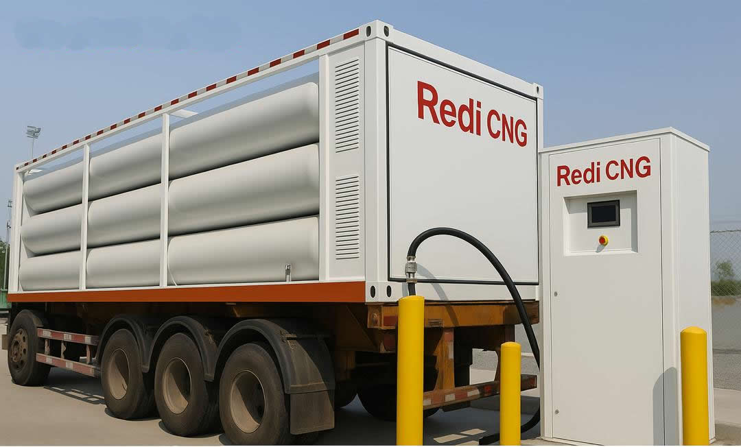
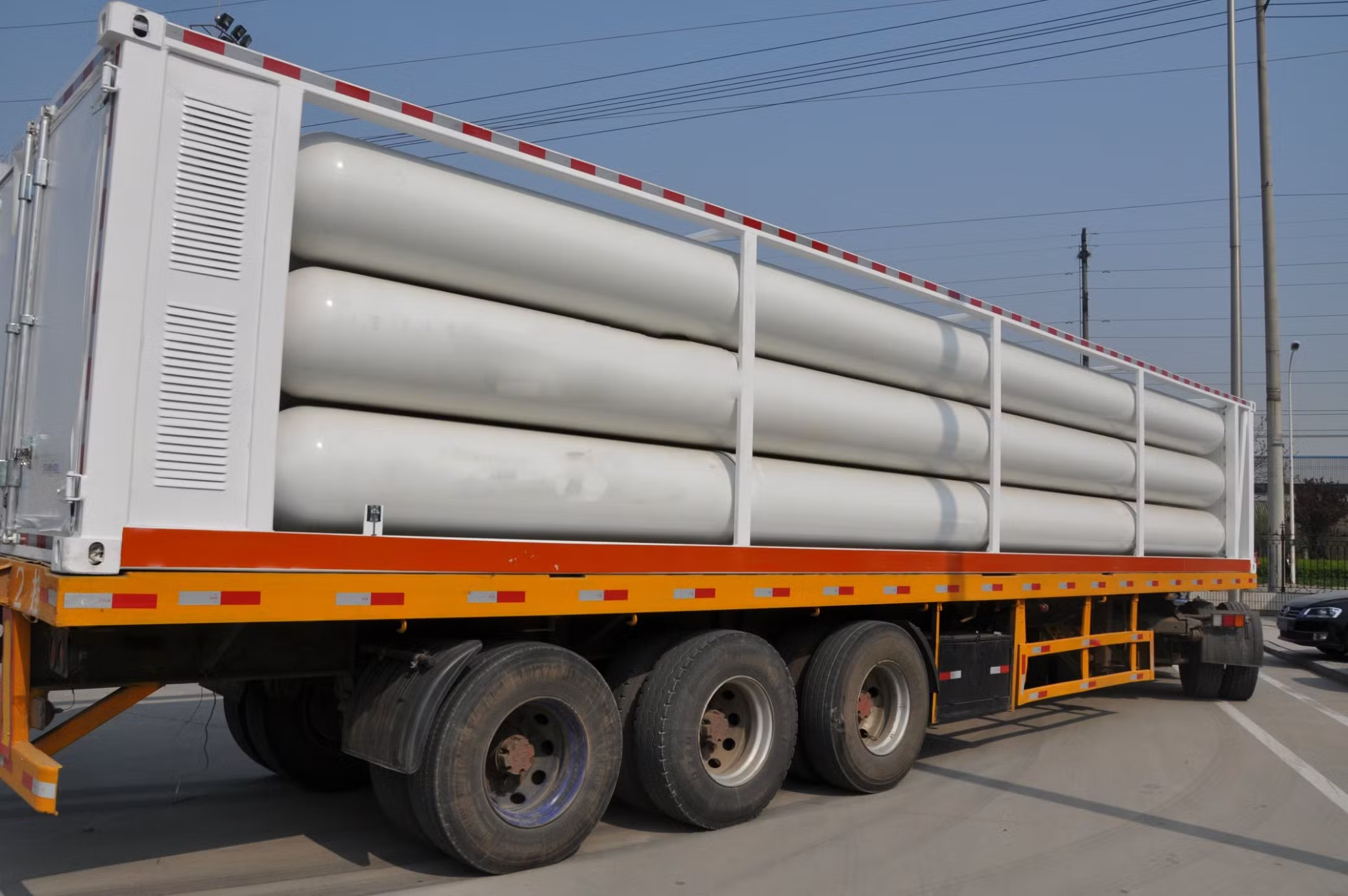
Certified vehicle conversions for Nigerian roads
Safe, standards‑compliant bi‑fuel and dual‑fuel conversions with parts availability and warranty support.
Conversion options
Spark‑ignition engines
Bi‑fuel petrol/CNG kits for cars and light vans; switch seamlessly when needed.
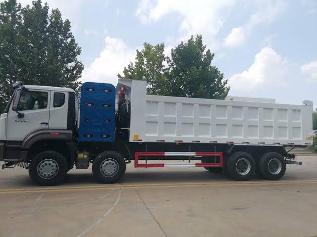
Diesel‑to‑Dual Fuel
Diesel substitution kits for heavy‑duty trucks and buses to cut cost and emissions.
Quality & Warranty
Certified cylinders, regulators and valves; technician training and post‑conversion support.
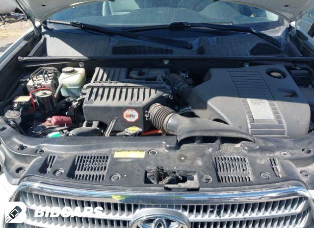
Step-by-step guide for conversion of V6 PFI vehicles


01
Pre-checks & planning (do not skip)
- Engine health: compression/leak-down, no misfires, coils/plugs (close plug gap by ~0.1 mm for CNG). Replace weak ignition parts.
- Space/layout: pick locations for the reducer (near heater hoses), rails (close to runners), ECU (dry/cool), filter/sensors, filler point, and cylinder.
- Compliance: components certified to ECE R110 / ISO 15500; follow local regulations (inspection, paperwork, insurance). Fire safety on site.
02
Mount the 80 L Type-2 cylinder (Redi CNG)
- Fit approved saddles & bands to OEM hard-points; use anti-abrasion pads; torque brackets to spec.
- Install the multivalve (with manual shut-off, PRD). Typical orientation in accordance with the supplier (often ≤30° from horizontal).
- Vent PRD to outside the cabin; ensure no kinks or blockages.
- Clearly label cylinder: “Redi CNG” + serial; bond to chassis ground.
Read more >>
03
Install the filler valve & route high-pressure (HP) line
- Choose an external fueling point (fuel door or rear quarter). Add a bulkhead union and dust cap.
- Route HP stainless/approved tube underbody through the tunnel/rails, away from heat/moving parts; clamp ≤50 cm spacing, edge guards at pass-throughs.
- Use only approved flare/compression fittings. No soldering. Leave a service loop for reducer connection. Pressure-test with inert gas first.
04
Mount reducer/vaporizer and low-pressure (LP) plumbing
- • Secure the reducer near heater hoses; tee into coolant circuit, purge air, verify flow.
- HP line → HP solenoid (if separate) → reducer.
- Reducer LP outlet → LP filter → AEB pressure/temperature/MAP sensor → two gas injector rails (3+3).
- Keep LP hoses short & equal length to each bank.
05
Fit intake runner nozzles (PFI)
- • For each of the 6 runners, drill & tap (e.g., M6×1) ~60–100 mm upstream of the intake valve at a 30–45° shallow angle to airflow.
- Use grease on the drill/tap to capture swarf; vacuum thoroughly; use gas-approved thread sealant.
- Install barbs; run equal-length hoses from each injector rail outlet to its runner barb.
06
Wire the AEB ECU & controls
- • ECU +12 V (fused) and clean chassis ground; switched IGN 12 V feed.
- RPM (coil/CAN per ECU guide), coolant temp, pressure/T sensors, gas injector loom, petrol injector intercepts (for cut/emulation), changeover switch in cabin, optional OBD.
- Map cylinder order/banks correctly; loom in split conduit; protect with grommets; avoid heat sources.
07
Leak tests (HP & LP)
- With inert gas (then CNG at station later): spray all joints, multivalve, reducer, filters, sensor block, rail barbs.
- LP side test at ~1–2 bar (reducer outlet). Fix any leaks before proceeding.
08
First start & switchover logic
- Start on petrol; verify normal operation.
- In AEB software, set coolant-temperature switchover to ~40–50 °C; enable pressure & RPM safety cut-offs; choose gentle changeover strategy.
09
Autocalibration (idle/cruise)
- Set engine parameters: 6-cyl, sequential PFI, reducer nominal pressure, injector type, nozzle size, bank assignment.
- Run idle calibration; hold 2,000–3,000 rpm no-load to fill in base map points.
10
Road tuning (load cells)
- Log trims: keep STFT/LTFT ≈ 0 ± 5% on CNG.
- Adjust gas map so gas injector times track petrol times across load without oscillations.
- Confirm smooth petrol↔gas changeover under steady throttle.
- If power drop is excessive: check reducer pressure stability, hose lengths, nozzle sizes, ignition health.
11
Final checks & documentation
- Confirm manual shutoff works; verify low-pressure cutback to petrol.
- Secure all clamps/looms; add heat shields near exhaust where needed.
- Label engine bay and fuel door: “Redi CNG Bi-Fuel” and emergency shut-off location.
- Provide owner pack: refueling steps, switch usage, emergency procedure, and service schedule (LP filter every 10–20k km, HP filter ~60k km or per manufacturer; cylinder inspection per regulation).
Bill of materials (typical AEB-based kit for PFI 6-cyl)
- AEB 6-cyl ECU (e.g., MP48/MP60 class) with full loom & changeover switch.
- 2× 3-cyl gas injector rails (or 1× 6-cyl rail), calibrated nozzles.
- Reducer/vaporizer sized for engine output (include HP shutoff solenoid if not integrated).
- LP filter (serviceable), AEB P/T/MAP sensor block.
- HP tube & fittings (ECE R110/ISO 15500), bulkheads, clamps, edge guards.
- LP hoses, barbs, equal-length runner hoses; M6×1 nozzles.
- 80 L Type-2 cylinder with multivalve + PRD, brackets/bands (Redi CNG label).
- Mounting brackets for components; grommets, conduit, fuses, ties, heat shields.
Practical tips (from field installs)
- Keep rails upright and as close to runners as possible to reduce transient delay.
- Short, equal hoses = better drivability.
- Reducer warmth matters: poor coolant flow = pressure dips under load.
- If your ECU supports it, enable OBD adaptation to keep trims centered.
- Typical CNG causes ~10–15% power drop; healthy ignition and correct nozzle sizing minimize this.
Safety & legal
- Perform all work to ECE R110 / ISO 15500.
- Use a certified inspector where required; no leaks accepted.
- Keep an ABC fire extinguisher handy, maintain ventilation, and disconnect the battery when drilling or tapping.
Step-by-step guide for conversion of GDI vehicles to CNG & Petrol


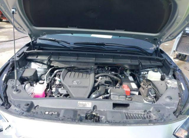
⚠️ Key difference from PFI → GDI (Gasoline Direct Injection):
- In GDI engines, petrol injectors are inside the combustion chamber (very high pressure, ~50–200 bar).
- Standard CNG port injection cannot directly replace GDI injection, so bi-fuel kits for GDI (like AEB’s DGi series, Prins Direct LiquiMax, BRC Sequent Direct, etc.) use parallel injection control:
- Petrol injectors remain active (small pilot dose for cooling/lubrication).
- Gas injectors are added in the intake manifold.
- ECU software blends CNG with petrol, typically 70–90% CNG, 10–30% petrol.
Thus, the installation is similar to PFI but with GDI-adapted ECU, wiring harness, and calibration strategy.
Redi-CNG Conversion Guide for V6 GDI Vehicles
01
Pre-checks & planning
- Engine: 3.5L V6 GDI (likely A25A/2GR-FKS variant).
- Health check: compression, injector spray patterns, HP fuel pump operation, ignition system.
- Verify space for: reducer (firewall side), twin injector rails, 80 L Type-2 cylinder, AEB DGi ECU, filter/sensors, filler point.
- Compliance: ECE R110 / ISO 15500, local Nigerian regulations.
02
Cylinder Placement (80 L Type-2 — Redi CNG)
- Location: Cargo bay floor or spare tire well, transverse mount.
- Multivalve left side, ≤30° tilt, PRD vented outside.
- Brackets: steel saddles with chassis rails; torque to spec.
- Label cylinder: Redi CNG.
Read more >>
03
Reducer (Vaporizer) Placement
- Mount near firewall (passenger side), tapping into heater hoses.
- Ensure constant coolant flow.
- Reducer feeds LP filter + AEB MAP/P/T sensor → dual injector rails (3+3).
04
Injector Rails & Runner Nozzles
- Drill/tap each runner (PFI-style) ~60–80 mm from intake valve at 30–45°.
- Equal hose lengths per bank.
- Mount front rail near radiator side bank; rear rail near firewall side bank.
- Label each: Redi CNG Rail (3).
05
ECU & Wiring (AEB DGi ECU)
- Use AEB DGi ECU (GDI-adapted) mounted in cabin/engine bay.
- Wiring:
- Petrol injector intercepts (special harness for high-pressure GDI control).
- Gas injector harness (6 ports).
- RPM, ignition, coolant temp, MAP/pressure sensors.
- Cabin switch.
- Optional OBD link for closed-loop fuel trims.
- ECU strategy: Petrol injectors stay active (pilot), CNG injectors carry bulk fueling.
06
Leak Testing
- HP (200–260 bar) → cylinder to reducer.
- LP (~1–2 bar) → reducer to rails.
- Leak spray at joints, reducer, rails, sensor block, barbs.
07
Calibration (GDI-specific)
- Software: AEB DGi Suite.
- Engine: V6 GDI, sequential.
- Autocalibration at idle & cruise.
- Road tune: light/medium/full load.
- Balance: target 70–80% CNG, 20–30% petrol injection.
- Monitor STFT/LTFT; trims within ±5%.
- Safety cut-offs: low gas pressure, injector failure, RPM loss.
- Expect ~5–10% petrol always injected for cooling.
08
Final Checks & Documentation
- Smooth switchover petrol ↔ CNG.
- Labels in engine bay & fuel door: “Toyota Highlander 2024 — Redi CNG Bi-Fuel (GDI)”.
- Maintenance: LP filter 10–20k km, HP filter 60k km, reducer service per manufacturer, cylinder inspection per regulation.
Bill of Materials (for GDI V6)
- AEB DGi ECU (6-cyl) with GDI harness & switch.
- Reducer/vaporizer sized for ~300 hp output.
- 2× 3-cyl injector rails + matched nozzles.
- LP filter + MAP/P/T sensor.
- HP tube/fittings, clamps, bulkhead unions.
- 80 L Type-2 cylinder (Redi CNG) with PRD multivalve.
- Brackets, grommets, conduit, fuses, relays, loom protectors.
The installation sequence is structurally the same as the PFI version, but wiring and calibration differ because of the GDI system.
Here’s the complete illustrated manual for converting the Toyota Highlander 2024 V6 GDI to a Redi CNG bi-fuel (CNG + Petrol) system. This set follows exactly the same structure as the PFI guide but adapted for GDI engines using the AEB DGi ECU.
Step-by-step guide for conversion of Dual Injection System (PFI + GDI)


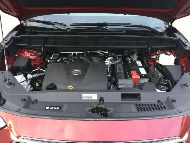
The Toyota Highlander 2020 V6 (3.5L 2GR-FKS) uses a dual injection system:
This means your CNG conversion must account for both injector systems. Most advanced ECUs (AEB DGi Dual, Prins VSI-2 DI, BRC SDI) handle this by:
- GDI (direct injectors) for high load and efficiency.
- PFI (port injectors) for light load and cylinder cleaning.
This means your CNG conversion must account for both injector systems. Most advanced ECUs (AEB DGi Dual, Prins VSI-2 DI, BRC SDI) handle this by:
- Intercepting both PFI and GDI injector signals.
- Adding gas injector rails into the intake runners (like PFI-only setups).
- Blending CNG with petrol while letting PFI/GDI injectors operate normally (though reduced fuel duty).
Redi-CNG Conversion Guide for V6 Dual PFI+GDI Vehicles
01
Pre-checks
- Engine: 3.5L V6 2GR-FKS, 295 hp.
- Confirm health of both fuel systems (PFI injectors + HP fuel pump + GDI injectors).
- Plan space for: 80 L cylinder, reducer, twin gas rails, ECU (dual control), filters/sensors, filler valve.
02
Cylinder (80 L Type-2, Redi CNG)
- Cargo bay mount, transverse, multivalve left-side, PRD vented.
- Brackets anchored to rails, pads to prevent abrasion.
- Label: “Redi CNG”.
Read more >>
03
Filler Valve & HP Line
- Filler near petrol cap, dust cover.
- HP tubing along chassis rail, clamps ≤50 cm.
- Pressure test with inert gas first.
04
Reducer Placement
- Firewall side (passenger corner), tied into heater hoses.
- Upright mount with bracket; ensure proper coolant flow.
- Output → LP filter → MAP/pressure sensor → injector rails.
05
Gas Injector Rails & Runner Nozzles
- Drill/tap 6 runners (30–45°, ~70 mm upstream of intake valves).
- Equal hose lengths per bank.
- Front bank rail near radiator side; rear bank rail near firewall.
- Short hoses for best transient response.
06
ECU & Wiring (AEB Dual-System ECU)
- ECU must handle PFI+GDI blend.
- Inputs:
- Petrol injector signals (both PFI and GDI).
- Gas injectors.
- RPM, MAP, coolant temp, pressure sensors.
- Outputs:
- Controls gas injectors.
- Manages petrol injector duty (reduces but doesn’t cut fully).
- Cabin switch for driver control.
07
Calibration
- Software: AEB DGi Dual.
- Engine type: V6 dual-injection.
- Autocalibrate at idle, then mid-load.
- Road test under light, medium, heavy loads.
- Typical blend: 60–80% CNG, 20–40% petrol (both PFI + GDI injectors continue to spray small amounts).
- Target trims within ±5%.
- Safety cut-offs: low gas pressure, RPM loss, injector fault.
08
Final Checks
- Leak test both HP and LP.
- Verify smooth petrol↔CNG switchover.
- Confirm that both petrol systems (PFI+GDI) remain functional with reduced load.
- Train driver: system always blends (never 100% CNG).
Comparison (Dual vs PFI vs GDI)
- • PFI-only (2010): 100% CNG possible, petrol injectors cut off.
- • GDI-only (2024): Always petrol pilot injection, 10–30%.
- • Dual PFI+GDI (2020): ECU coordinates both sets; ~20–40% petrol always injected, even at light load.
This conversion is a hybrid strategy — you install CNG rails like PFI, but the ECU manages both petrol systems like GDI. It’s essentially the most complex setup.
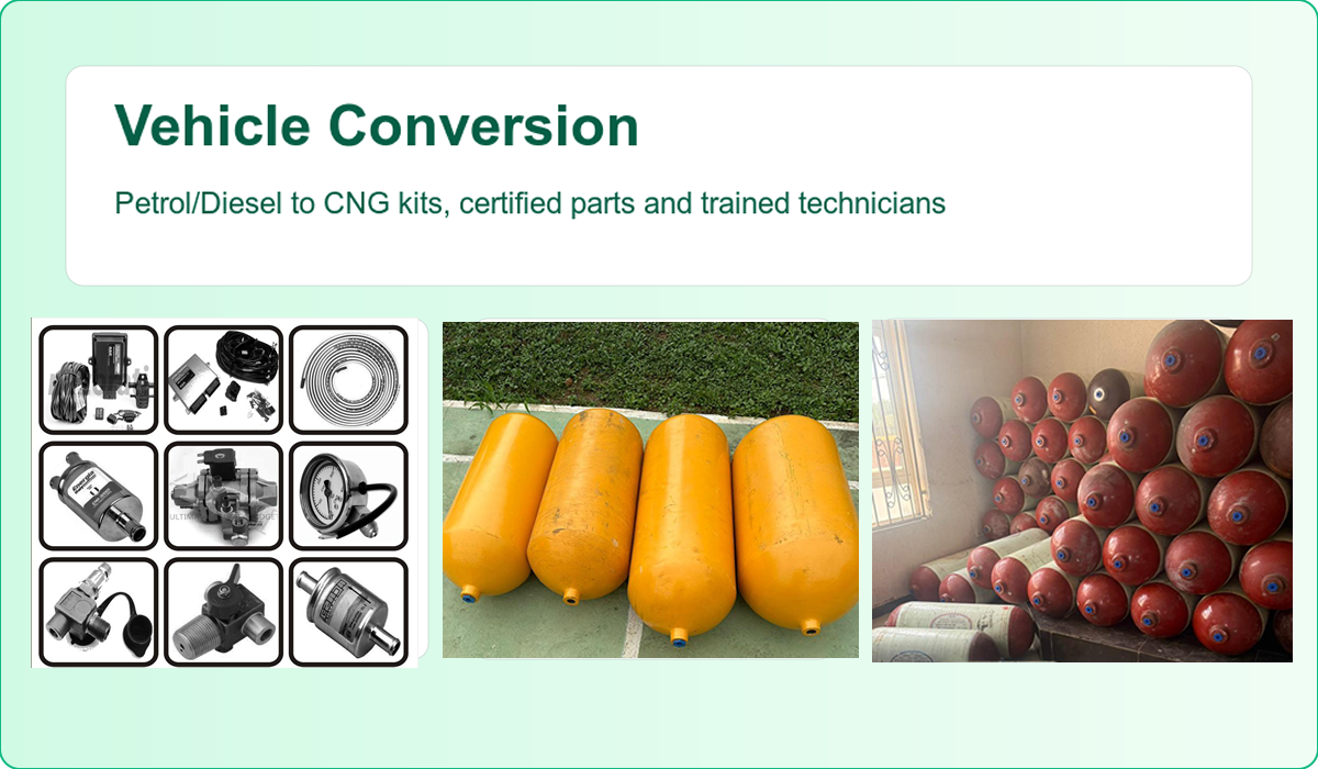
Ready to switch to CNG?
Lower fuel costs, fewer emissions, stronger margins. We help you convert and keep moving.

